Aberration
Brief description of wavefront error (WFE) modelling and how it is implemented in PAOS.
Introduction
In optics, aberration is a property of optical systems, that causes light to be spread out over some region of space rather than focused to a point. An aberration causes an image-forming optical system to depart from the prediction of paraxial optics (see Paraxial region), producing an image which is not sharp. The WFE and the resulting image distortion depend on the type of aberration.
The WFE can be modelled as a superposition of Zernike polynomials that describe Optical aberrations and a surface error field (SFE) with a given power spectral density (PSD) and surface roughness (SR) (see PSD and SR). That is, the WFE can be decomposed into low frequency and medium-to-high frequency contributors.
Aberration maps from e.g. interferometric measurements are also of great importance as the optical system is manufactured (see Grid Sag).
Useful concepts to estimate image quality such as
are discussed in the following sections for self-consistency.
Strehl ratio
For large aberrations, the image size is larger than the Airy disk. From the conservation of energy, the irradiance at the center of the image has to decrease when the image size increases.
Image quality can be assessed using the Strehl ratio (see e.g. Malacara-Hernández, Daniel & Malacaea-Hernandez, Zacarias & Malacara, Zacarias. (2005). Handbook of Optical Design Second Edition.), i.e. the ratio of the irradiance at the center of the aberrated PSF to that of an ideal Airy function, which is approximated as
where \(k\) is the wavenumber and \(\sigma_{W}\) is the wavefront variance, i.e. the square of the rms wavefront deviation. This expression is adequate to estimate the image quality for Strehl ratios as low as \(0.5\).
Encircled energy
Another way to assess image quality is by estimating the radial (or encircled) energy distribution of the PSF.
The encircled energy can be obtained from the spot diagram by counting the number of points in the diagram, inside of circles with different diameters. Alternatively, the fraction of the encircled energy \(f\) in function of the encircled energy aperture radius \(R_f\) in image-space-normalized units can be computed as
For an ideal diffraction limited system \(R_{0.838} = 1.22\), and \(R_{0.910} = 2.26\) are the energy encircled in the first and second Airy null, respectively. For an optical system that can be described using a single \(F_\#\) the normalised radii can be expressed in units of wavelengths using
Fig. 20 reports the encircled energy in function of \(R_f\) for an aberrated PSF and a diffraction limited PSF. The \(83.8\%\) and \(91.0\%\) levels are marked in red for the aberrated PSF, and in black for the diffraction limited PSF.
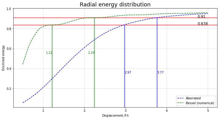
Fig. 20 Encircled energy
Optical aberrations
PAOS models an optical aberration using a series of Zernike polynomials, up to a specified radial order. This is handled by the class Zernike and its child class PolyOrthoNorm.
Following Laksminarayan & Fleck, Journal of Modern Optics (2011), the function describing an arbitrary wavefront wavefront in polar coordinates W(\(r, \theta\)) can be expanded in terms of a sequence of Zernike polynomials as
where \(C_{n}^{m}\) are the coefficient of the Zernike polynomial \(Z_{n}^{m} (\rho, \theta)\).
The first three terms in (47) describe Piston and Tilt aberrations and can be neglected.
Non-normalised Zernike polynomials are defined in PAOS as:
where the radial polynomial is normalized such that \(R_{n}^{m}(\rho = 1) = 1\), or
with \(\delta_{mn}\) the Kroneker delta function, and the average operator \(\left<\right>\) is intended over the pupil.
Using polar elliptical coordinates allows PAOS to describe pupils that are elliptical in shape as well as circular:
where \(x_{pup}\) and \(y_{pup}\) are the pupil physical coordinates and \(a\) and \(b\) are the pupil semi-major and semi-minor axes, respectively.
Fig. 21 reports surface plots of the Zernike polynomial sequence up to radial order \(n=10\). The name of the classical aberration associated with some of them is also provided (figure taken from Laksminarayan & Fleck, Journal of Modern Optics (2011)).
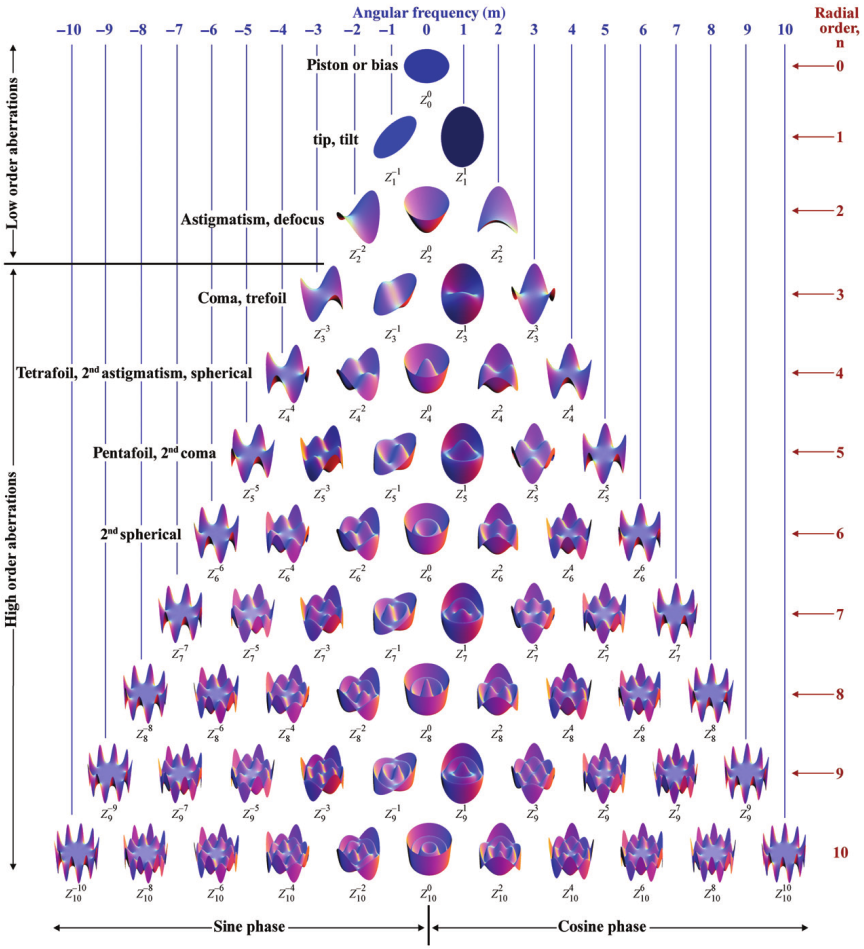
Fig. 21 Zernike polynomials surface plots
PAOS can generate both ortho-normal polynomials and orthogonal polynomials and the ordering can be either ANSI (default), or Noll, or Fringe, or Standard (see e.g. Born and Wolf, Principles of Optics, (1999)).
Example of an aberrated pupil
An example of aberrated PSFs at the Ariel Telescope exit pupil is shown in Fig. 22.
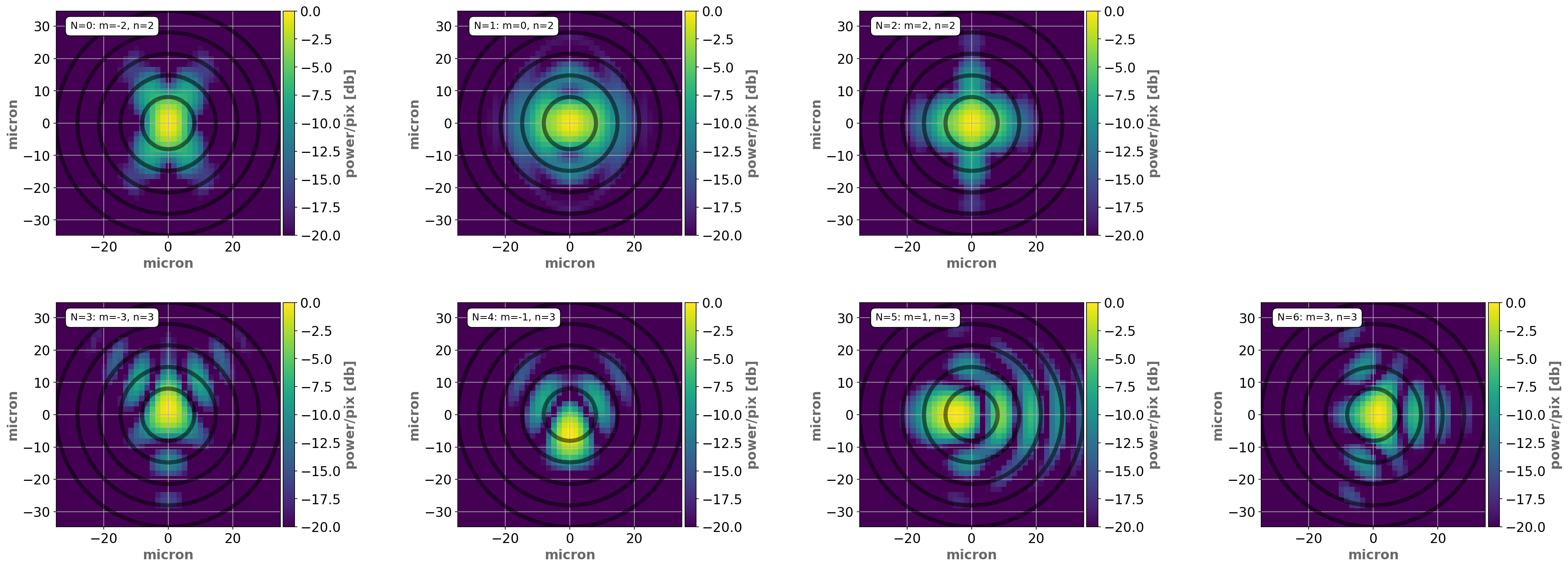
Fig. 22 Ariel Telescope exit pupil PSFs for different aberrations and same SFE
In this figure, the same Surface Form Error (SFE) of \(50 \ \textrm{nm}\) is allocated to different optical aberrations. Starting from the top left panel (oblique Astigmatism), seven such simulations are shown, in ascending Ansi order.
Each aberration has a different impact on optical quality, requiring a detailed analysis to translate e.g. a scientific requirement on optical quality into a WFE allocation.
PSD and SR
Optical elements exhibit medium to high frequency defects produced during manufacturing (e.g. using diamond turning machines). These types of defects reduce the Strehl ratio without significantly altering the PSF’s fundamental shape.
The resulting aberrations can be statistically described relative to the spatial scales of interest using a parameterized Power Spectral Density (PSD) specification (Church1991) or as surface roughness (SR) using a zero-mean random Gaussian field with variance \(\sigma_{G}\).
PAOS implements this functionality in the PSD class.
Grid Sag
The capability to insert a measured surface map into an optical chain is provided by PAOS thanks to the method paos.classes.wfo.WFO.grid_sag.
The user can point PAOS to a binary (.npy) file that contains a dictionary with the grid sag in wavelength units, with given sampling along X and Y, and any offset in pixel that one wishes to apply. Then, PAOS shifts the sag, resamples it to the current sampling and makes sure the resulting array has the correct shape, before applying it to the wavefront.